Using a Strobe Light to Observe Uniform Circular Motion |
For this experiment, it is important to know how a multimeter works.
|
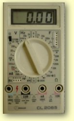
A multimeter such as this one can be used to measure voltage, current, and frequency, among others. In order to get the desired measurement, two things are necessary: 1. selecting the appropriate function on the dial and 2. plugging what is being measured into the correct sockets. For one measurement, there are several choices on the dial. For voltage, the range is 0 to 200 millivolts ("200m" on the dial), 200 mV to 2 volts ("2" on the dial), 2 V up to 20 V ("20") and so forth. For frequency, the dial goes from 0 to 2000 Hz ("2k" on the dial), 2000 Hz to 20,000Hz ("20k") and so forh. |
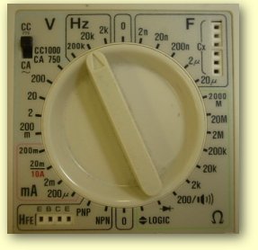 Fig. 2. Closeup of the dial. 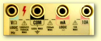 Fig. 3. The four sockets on the multimeter. In this experiment, measuring both voltage and frequency will require only the first and second sockets. |
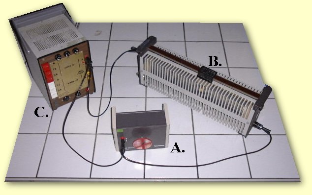
Fig. 4. This is the circuit which will make the disk turn at different speeds. A. is the rotating disk, B. is the sliding switch and C. is the power supply set to 6V DC.
|
|
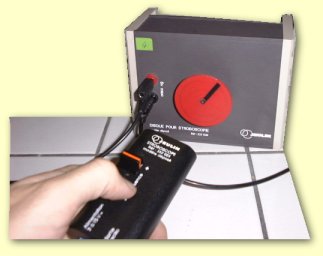
Fig. 5. The strobe is pointed at the rotating disk. The speed of the strobe is set to its highest speed and then very gradually slowed down until a fixed image is obtained. The image could be any number of black bars or just one (see below). |
|
|
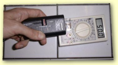
Fig. 6. Then the light sensitive diode is plugged into the multimeter and the multimeter is set to 2k Hz. The frequency of the strobe can be measured if the strobe is flashed on the light sensitive diode. |
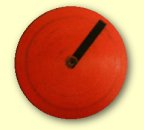
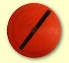
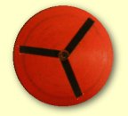
Fig. 7. Disk 1 has one slow-moving bar, Disk 2 has one stationary bar, Disk 3 has two stationary bars, and Disk 4 has three stationary bars.
Questions 2. Explain clearly what this number (the answer to the first question) represents. 3. In Figure 7, disk 2 is visible when the strobe is flashing at exactly the same frequency as the disk is turning. Explain what is happining which gives the impression that the disk has stopped. 4. Figure 7's disk 2 could also be visible when the strobe is flashing at half the frequency of the disk. Explain why this is possible and say whether or not the same image could be seen if the strobe is flashing at one third the frequency of the disk. 5. Based on your answer to number 4, explain how you could regulate the strobe's frequency to be sure you were looking at the disk's actual speed and not a fraction of it. 6. Explain how the image in Figure 7's disks 3 and 4 could have been formed. 7. A student doing this experiment got the following results: as she slowed down the strobe from 500 to 40 flashes per second, she noticed that a single black bar appeared immobile at the frequencies 150 Hz, 75 Hz and 50 Hz. a)What is the disk's frequency of rotation? b)What would she see if she put the strobe at 300 Hz? (answer using any of the four possibilities from Figure 7) c) How could she get all the other possibilities? (base your answers on all the disks in Figure 7 which you did not mention in part b of this question) 8. Films from the beginning of this century showed 16 to 18 images per second instead of the 24 per second seen in today's cinemas. French television broadcasts 25 images per second. When classic films from the Lumière brothers or Charlie Chaplin are shown on television, what visual effect does this numerical inequality produce concerning the action in the film? Explain. |
If you would like to send your homework to Mr. Damon by e-mail, click here for a complete set of instructions on how to do that.
This page was last updated on October 8th, 1999.
![]()
Comments? Questions? Write me an e-mail at this address: damon@chez.com . Do not forget to put your NAME and CLASS in any e-mail you send me. If you want me to respond by e-mail, indicate your e-mail address, please.